
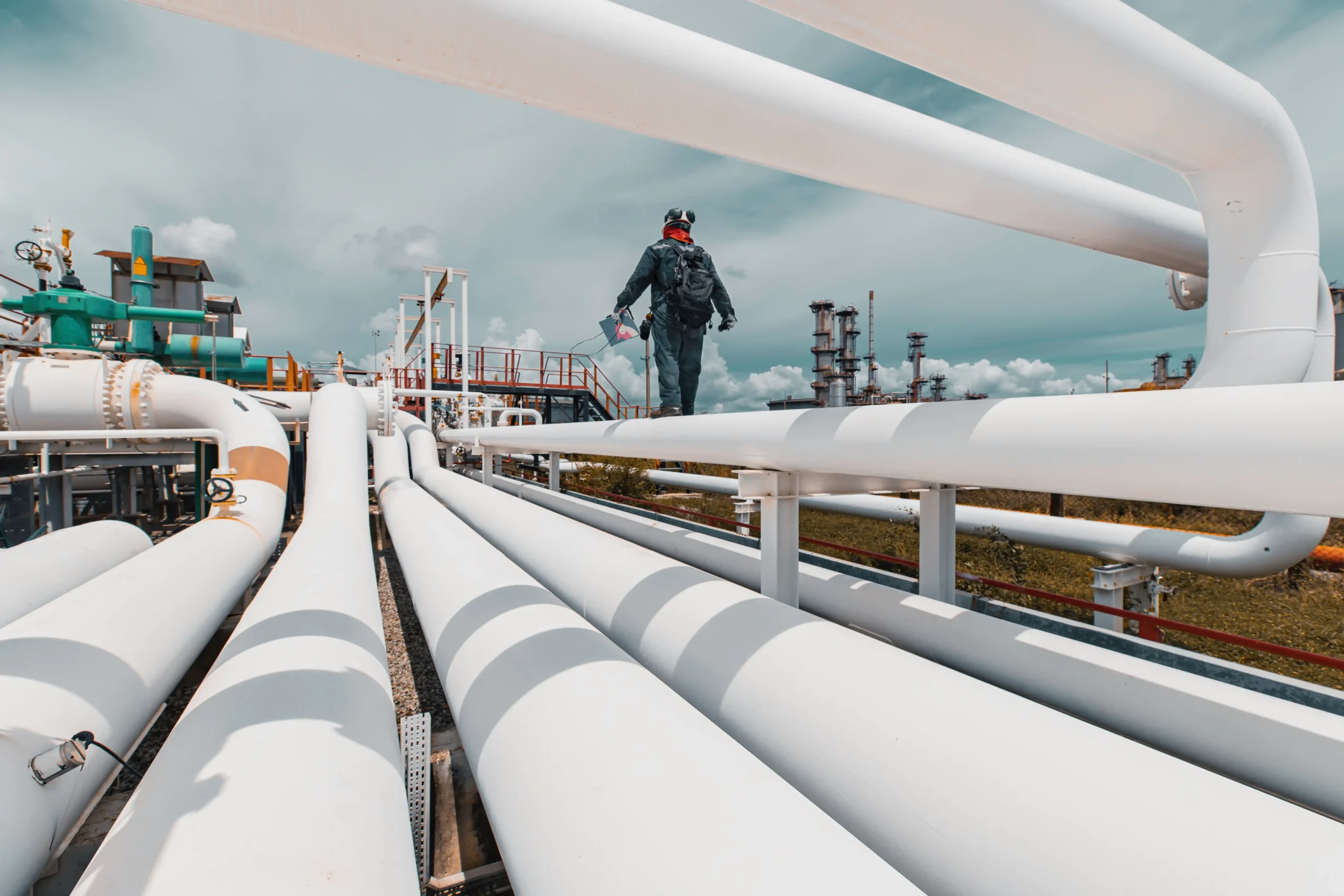
The question underneath most piping design inquiries is a scoping question, not a technical one. Someone has a process line to build, modify or defend, and has to decide what to buy: the drawings that say where the pipe goes, the analysis that says the pipe will survive there, or both. The two are sold under similar names and priced very differently.
This is the boundary. What a layout deliverable settles, what a stress deliverable settles, how ASME B31.3 decides which lines need the second one, and what each handoff has to carry.
Key takeaways
- Layout settles size, material, wall thickness, route and deadweight support. All of it can be done by rule.
- Stress analysis settles what happens when the line heats up, moves, and pulls on the equipment it is bolted to. That cannot be done by rule on most hot lines.
- ASME B31.3 para. 319.4 requires a formal flexibility analysis on every system except three narrow cases.
- A 12 in. line restrained between two anchors can push on those anchors with roughly 800,000 lbf. That is the number layout rules do not produce.
- The critical line list is the formal handoff. If nobody has written one, nobody has decided which lines get analyzed.
What do piping design services include?
Piping design services cover the decisions that fix the geometry and the material of a system. Pipe size comes from the process: flow rate, fluid and allowable pressure drop. Material comes from the fluid, the service and the temperature. Wall thickness and component class come from the design pressure and design temperature. Then insulation, then routing for hydraulics, serviceability, venting and draining, then support of the pipe’s own weight.
In the SPED technical brief Pipe Stress for Pipers, David Diehl of Intergraph sets the split in two lists. The piping designer handles “positioning equipment, sizing pipe, routing pipe, supporting weight.” The piping engineer “steps in when required” for “assuring safe design, calculating equipment and component loads, sizing supports.”
That word “required” is the whole commercial question. Most of a plant’s lines never need the second list. The ones that do will not tell you by looking.
What layout settles, and by what rule
Almost everything on the layout side has a code paragraph or a published table behind it, which is why it can be scoped, priced and checked straightforwardly.
Wall thickness comes from ASME B31.3 para. 304.1.1 and its equation for straight pipe, t = PD / 2(SEW + PY), with a corrosion allowance added and the mill minus tolerance accounted for. The design pressure that feeds it is defined in para. 301.2 as the most severe coincident internal or external pressure and temperature expected in service, and the design temperature in para. 301.3 as the temperature at which, under the coincident pressure, the greatest thickness or highest component rating is required. Fabricated branch connections pick up added reinforcement under para. 304.3.3 when the components do not supply it inherently.
Deadweight support is also rules based. Diehl points to ASME B31.1 and MSS SP-69 and gives four steps a designer can work through without an analyst: support concentrated loads such as valves; use the maximum span spacing on horizontal straight runs and three quarters of that span on horizontal runs with bends; support risers at one or more locations, preferring locations above the center of gravity; and use the steel that is already there.
Nothing in that list involves temperature change. That is the gap.
Where stress analysis begins
Stress analysis begins at thermal strain, because thermal strain is the one load that layout rules do not touch and intuition reads backwards.
Diehl works the arithmetic for a 12 in. carbon steel line, outside diameter 12.75 in. and wall 0.375 in., so a metal area of 14.58 in². With a modulus of 29.5 x 10⁶ psi and a thermal strain of 1.879 x 10⁻³, which is about two and a quarter inches of growth in every hundred feet of run, a line locked between two anchors develops F = AEα = 808,000 lbf on those anchors, “or buckle.”
Nobody draws that force on a plan. It appears only when the model knows the route, the restraints and the temperature at the same time, and it is why a layout that looks tidy can be the expensive one. Diehl’s conclusion is blunt: “Because of the interaction of thermal growth and piping layout, most humans cannot predict the effects of thermal strain in piping systems.”
The code agrees in its own way. ASME B31.3 para. 319.4 requires a formal analysis of adequate flexibility for all piping systems, with three exceptions:
- Systems that duplicate an operating installation with a successful service record.
- Systems that can be judged adequate by comparison with previously analyzed systems.
- Systems of uniform size with no more than two anchor points and no intermediate restraints, that also fall inside the Code’s empirical equation, Dy / (L − U)² ≤ K1, where D is the outside diameter, y the resultant displacement to be absorbed, L the developed length between anchors and U the straight line distance between them.
The Code supplies its own caution with that third case: no general proof can be offered to assure that the formula will yield accurate or consistently conservative results, and it does not assure that terminal reactions stay inside allowable limits. A line can pass the flexibility screen and still tear a pump nozzle off.
Which lines get a formal stress analysis?
A project settles that with a critical line list, written before layout is finished so designers know which routes are about to be argued with. Diehl calls it “the handoff for ensuring safe design” and gives a one line screen for a quick read: outside diameter multiplied by the temperature change, greater than 1,450.
The fuller sample list he reproduces, from Sam Kannappan’s Introduction to Pipe Stress Analysis, flags:
- Lines 3 in. and larger connected to rotating equipment, subject to differential settlement of connected equipment or supports, or running below 20 F.
- Lines connected to reciprocating equipment, including compressor suction and discharge.
- Lines 4 in. and larger connected to air coolers, steam generators or fired heater tube sections.
- Lines 6 in. and larger at 250 F and above, all lines at 600 F and above, and all lines 16 in. and larger.
- All alloy lines, and high pressure lines over 2,000 psi.
- Lines subject to external pressure, and thin wall pipe 18 in. and over with a diameter to thickness ratio above 90.
- Lines requiring expansion joints or proprietary couplings, underground process lines, and lined or jacketed piping.
- Lines in critical service, pressure relief systems, and relief valve stacks with an inlet pressure above 150 psig.
Read that list as a scoping tool rather than a code requirement. It is one published sample, and thresholds move from project to project. What does not move is the principle: the decision is made deliberately, in writing, and early.
The boundary, deliverable by deliverable
The clearest way to tell the two scopes apart is by the question each one answers.
| The question | Settled by piping design | Settled by stress analysis |
|---|---|---|
| How big is the pipe? | Flow rate, fluid, pressure drop | Not revisited, unless flexibility forces a change |
| How thick is the wall? | B31.3 para. 304.1.1, design pressure and temperature | Checked against sustained and occasional stress limits |
| Where does the pipe run? | Hydraulics, access, venting, draining, clash | Re-routed where the route has no flexibility |
| Where are the supports? | Span tables, B31.1 and MSS SP-69, concentrated loads | Type and load of each one, anchors, guides, springs, snubbers |
| What does the line do when it heats? | Not answered | Displacement stress range against the code allowable |
| What load reaches the pump or vessel? | Not answered | Nozzle forces and moments against OEM or code limits |
| What happens in an upset? | Not answered | Seismic, wind, relief discharge, fluid transient load cases |
The displacement stress range in row five is where the fatigue argument lives. The allowable, SA = f(1.25Sc + 0.25Sh), carries a cycle factor f that runs from 1.0 for systems up to about 7,000 cycles down to 0.3 above two million, so a line that cycles daily is judged on a different allowable than one that heats up once a year. The calculated range has to stay under it.
The handoff runs in both directions
The stress engineer’s first job is not analysis. It is conversion. Diehl describes it as turning the system “analog,” which may be “a sketch, a stress isometric, a concept,” into a digital model, and notes that “there can be several competing interpretations of this analog to digital conversion.” Two analysts given the same isometric can build two defensible models.
Then come the load cases, which the designer rarely sees written down: the system in operation, at startup, and in anticipated upsets. Then the acceptance criteria, which come from three different places at once. Equipment load limits come from industry standards for pumps, compressors, turbines and heaters. Deflection limits, maximum sag and slide, come from company standards. Stress limits come from the piping code.
And then the results go back. Displacements matter for clash checking and for sag and support liftoff. Forces and moments matter for sizing supports and restraints, checking flange loads and evaluating equipment loads. Where something fails, the fix is tested in the model and, in Diehl’s words, “send proposed changes back to the designer for approval.”
That loop is the part buyers underestimate. The analysis is not a certificate issued at the end of a layout. It is an argument with the layout, and the layout usually loses two or three rounds.
Which scope do you actually need?
Three situations cover most inquiries.
A new system, nothing built yet. You need both, in one engagement, with the critical line list written before routing is frozen. Buying layout alone and bidding the analysis afterward means paying twice for the routes that have to change.
A modification to an existing system. A tie-in, a new branch, a replaced pump, a changed operating temperature. Layout scope is small and analysis scope is not, because a modification changes the flexibility of everything attached to it. B31.3’s duplicate system exemption does not apply to a system you have altered.
An existing system that is misbehaving. Cracked supports, a leaking flange, a pump that keeps losing alignment, a line that bangs. There is no layout deliverable here at all. There is a model of what is installed, a set of load cases that explain the symptom, and a ranked list of changes. Fluid transient work and nozzle load evaluation usually start this way.
How XCEED scopes piping design and pipe stress analysis
XCEED Engineering delivers end-to-end piping system design and pipe stress analysis, from concept through final construction, designing to ASME B31.1 Power Piping, ASME B31.3 Process Piping and ASME Boiler & Pressure Vessel Code, Section III.
In practice that means the two scopes on this page are carried inside one engagement rather than traded across a contract boundary. Thermal, weight, seismic, wind and occasional load cases are evaluated together. Nozzle loads are managed against OEM limits, or verified by analysis where the limits are restrictive or unknown. Support design uses hand calculations for rapid screening and finite element analysis for complex load paths and localized effects, with existing supports reused and upgraded where that is feasible. Faulted and transient cases, including seismic, water hammer and relief events, are run as nonlinear and time history analyses.
Where a system is already degraded, pipe stress analysis is combined with targeted FEA for fitness-for-service style evaluation, temporary clamp and patch assessment, and outage deferral strategies with an engineering basis. For skid mounted and packaged systems the same work sits under process system engineering, and for a narrower piece of work the scope is described under pipe stress analysis services.
Frequently asked questions
What do piping design services include?
Pipe sizing from flow rate, fluid and allowable pressure drop; material selection from fluid, service and temperature; wall thickness and component class from design pressure and design temperature; insulation; routing for hydraulics, serviceability, venting and draining; and deadweight support. Diehl’s split in the SPED brief is the clean statement of it: the designer positions equipment, sizes pipe, routes pipe and supports weight, and the engineer assures safe design, calculates equipment and component loads, and sizes supports.
Is pipe stress analysis part of piping design?
It is a separate deliverable that changes the design. Layout produces drawings. Stress analysis produces load cases, stresses, support loads, nozzle loads and displacements, then sends changes back to the layout for approval. If a quote covers only drawings, the flexibility question has not been answered.
When does ASME B31.3 require a formal flexibility analysis?
Para. 319.4 requires it for every piping system except three cases: a duplicate of an operating installation with a successful service record, a system that can be judged adequate by comparison with previously analyzed systems, and a system of uniform size with no more than two anchor points and no intermediate restraints that falls inside the Code’s empirical equation. The Code warns that no general proof can be offered that the formula yields accurate or consistently conservative results.
Which lines need a pipe stress analysis?
The project’s critical line list decides. The sample list reproduced in the SPED brief flags lines 3 in. and larger on rotating equipment, lines 6 in. and larger at 250 F and above, all lines at 600 F and above, all lines 16 in. and larger, all alloy lines, high pressure lines over 2,000 psi, underground process lines, lined and jacketed piping, lines in critical service, and pressure relief systems. The quick screen is outside diameter times temperature change greater than 1,450.
Can you buy layout and analysis from two different firms?
You can, and the risk is the handoff. The analyst needs the route, the restraint positions, the design conditions, the material and the equipment nozzle allowables before the analysis means anything, and the results come back as changes to that route and those restraints. Every loop through two organizations costs schedule. Where one firm carries both, the iteration happens inside a single model.
Talk to XCEED about a piping scope
If you are deciding what to put out for quote, the useful first step is naming the lines. Design pressure and temperature, size, material, what the line connects to and whether anything rotates at either end will tell you within an hour whether you are buying a layout, an analysis, or both.
See what XCEED covers under pipe stress analysis, or contact our team to scope a piping design and analysis package for your system.
Sources: David Diehl, P.E., Intergraph, “Pipe Stress for Pipers,” SPED 2011 Technical Briefs, including the sample critical line list reproduced from Sam Kannappan, P.E., Introduction to Pipe Stress Analysis, ABI Enterprises, 2008; ASME B31.3 Process Piping paras. 301.2, 301.3, 304.1.1, 304.3.3 and 319.4, as summarized by Piping World and Forgepoint Mechanical Design; ASME B31.1 Power Piping and MSS SP-69 for support spacing.