
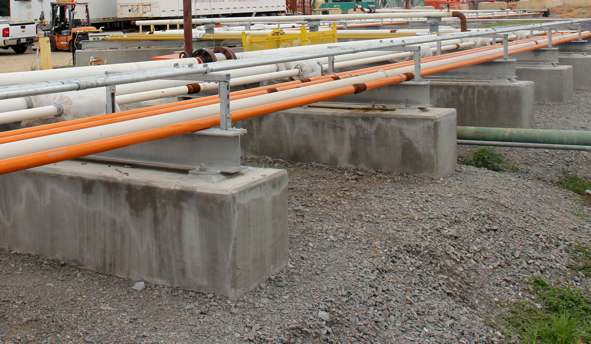
Pipe support design is the engineering work of deciding where a piping system is held, what each support has to carry, and how each one is detailed so the pipe stays inside code stress limits through every load it will see. Pipe support analysis is the verification half of the same job: you calculate the load at each location, then prove that the support, its attachment, and the steel or concrete underneath it can take that load.
Supports are usually the cheapest part of a piping system and the most common reason a system fails its stress check. A layout that passes on deadweight alone can fail the moment thermal growth, a seismic case, or a water hammer event is added. This guide covers what a support has to do, how spacing is set, where hand calculations stop and finite element analysis starts, and what a defensible support package contains.
What a pipe support has to do
Every support is a compromise between holding the pipe still and letting it move. Four jobs have to be balanced at once:
- Carry the deadweight. The pipe, its contents, its insulation, and any valves or flanges hanging off it.
- Allow thermal growth. A hot line grows. If a support holds it where it wants to move, the load goes into the pipe as stress and into the equipment nozzle as force.
- Resist occasional loads. Seismic, wind, relief valve discharge, and fluid transients act for seconds and can govern the design.
- Transfer the load somewhere real. A support is only as good as the beam, the sleeper, or the concrete it lands on.
Get the balance wrong in one direction and you overspend on steel. Get it wrong in the other and the system fails its stress check, or it passes on paper and moves in the field.
The load cases that decide a support
XCEED Engineering evaluates thermal, weight, seismic, wind, and occasional load cases on piping systems. Each one drives a different part of the support design:
- Weight sets the spacing and the size of the shoe or hanger.
- Thermal decides whether a location gets a rigid support, a guide, a spring, or nothing at all.
- Seismic governs lateral restraint, and on nonlinear systems it brings in support gaps and snubber behavior.
- Fluid transients such as water hammer produce short, high loads that no deadweight-sized support was ever meant to take.
The interaction matters more than any single case. Piping flexibility drives stress, support loads, equipment nozzle loads, and thermal growth behavior at the same time, and small routing or support changes can create outsized impacts. Moving one guide six feet can relieve a nozzle and overload a hanger twenty feet away.
How far apart supports can go
The starting point for spacing on a horizontal run is ASME B31.1, Table 121.5-1, which gives suggested maximum support spans for standard weight steel pipe. For water service the suggested span runs from 7 ft at NPS 1 to 32 ft at NPS 24. The same table gives longer spans for steam, gas, and air service — 9 ft at NPS 1 up to 42 ft at NPS 24 — because the pipe is carrying a lighter fluid.
Two things about that table are misread constantly. It is a suggested starting point, not an allowable. And it does not hold where a concentrated load sits in the span — a valve, a flange, a flow meter, or a branch connection pulls the span down, sometimes by half. Spacing off the table and then adding a gate valve mid-span is one of the more common ways a support layout quietly stops being code compliant.
The B31.1 spans are derived for a straight, uniformly loaded horizontal run on fixed beam supports, sized to keep bending stress under 2,300 psi and sag under 0.1 in. Change any of those conditions — a riser, a concentrated weight, a span that ends at an elbow, a line that has to drain — and the span has to be recalculated rather than read off the chart.
The six steps of pipe support design and analysis
- Build and validate the model. Route, sizes, materials, operating and design conditions, equipment locations and nozzle stiffnesses. A support answer is only as good as the model it came out of.
- Set preliminary spacing and support types. Start from the code spacing table, then adjust for concentrated loads, drainage, and where thermal movement will be largest.
- Run every load case. Weight, thermal, seismic, wind, and occasional loads, including transients where the system can see them.
- Read the loads back out. Every support gets a load in each case, and every load has to be checked against the support’s capacity and against the nozzle limits it feeds.
- Check the attachment and the structure. The shoe, the trunnion, the lug, the weld, and the beam or concrete underneath. This is where local stress work is needed and where a system-level pipe stress model stops being enough.
- Detail it so it can be built. Clear, constructible support details, dimensioned from something the crew can find in the field, with as-built documentation that will still make sense at the next modification.
Where hand calculations stop and FEA starts
Both belong in the same package. XCEED uses hand calculations for rapid screening and verification, and finite element analysis for complex load paths and localized effects. The line between them is usually the point at which load stops travelling through simple beam behavior.
Hand calculations are enough for span checks, standard hangers, simple shoes on a sleeper, and the first pass over a whole system. They are fast, they are auditable, and on most lines they are the right answer.
Finite element analysis earns its place when the load path is not simple: a trunnion or lug welded directly to the pipe wall, local shell stress at a support on a large diameter thin wall line, a nozzle-to-shell region where the equipment limits are restrictive or unknown, or an attachment whose flexibility changes the loads the system model predicted. Nozzle load analysis is the clearest case of this — equipment nozzles often govern what a support layout is allowed to do, and when the catalog limit is the obstacle, detailed analysis is what demonstrates real capacity.
The codes the work is designed to
XCEED designs to the requirements of applicable industry codes, and in piping the common ones are ASME B31.1 Power Piping, ASME B31.3 Process Piping, and the ASME Boiler & Pressure Vessel Code, Section III. Which code governs is a project decision, not a preference, and it changes the allowables, the load case combinations, and the documentation a reviewer will expect. The assumptions built into a stress analysis are what the code review actually examines.
Audit-ready documentation matters more in this discipline than in most. In regulated plants the support calculation is a record, and it has to be legible to somebody who was not in the room when it was made.
Adding supports is rarely the cheapest fix
When a stress check fails, the reflex is to add a restraint. It is often the most expensive available answer, because every new support carries a design, a detail, a material buy, a weld, an inspection, and outage time to install.
Cheaper levers usually exist:
- Reuse or upgrade what is already there. An existing support that is modified is faster and cheaper than a new location, and XCEED reuses and upgrades existing supports where it is feasible.
- Move a support rather than add one. Relocating a guide to where thermal growth is smaller can relieve both the pipe and the nozzle.
- Design out the maintenance-intensive parts. Snubbers in particular carry a test and inspection burden for the life of the plant, and minimizing them where appropriate lowers cost long after construction.
- Standardize the details. Repeating a small number of support types reduces procurement and install time and makes field errors less likely.
- Design for access. Supports that can be reached are supports that get inspected.
XCEED states that targeted, practical engineering of this kind reduces project costs and timelines by up to 25%, and reports cutting project costs by nearly 25% on high-pressure, fixed-timeline work such as capital scope reductions at highly regulated facilities.
Supports on a system that is already degraded
Support work on an operating plant often starts with an inspection finding rather than a design. When thinning, cracking, or a through-wall leak turns up, the support question changes: what can this line still carry, and for how long. XCEED combines pipe stress analysis with targeted FEA to determine operability and safe-run intervals, including fitness-for-service style evaluations of degraded sections, the effect of temporary clamps and patches, and outage deferral strategies with an engineering basis and a monitoring plan.
Working with XCEED Engineering on pipe support analysis
XCEED Engineering and Consulting, P.C. was founded in 2016 to solve critical needs in regulated environments, and works across nuclear, power, process, and industrial facilities from its office at 1580 Elmwood Ave in Rochester, New York. Pipe Support Analysis is a named capability on its pipe stress analysis team: each support is evaluated to carry the right load at the right time, using hand calculations for screening, FEA for complex load paths and localized effects, reuse of existing supports where feasible, and constructible details written to minimize outage time.
If you have a support layout that will not pass, a nozzle that will not accept the load, or an inspection finding on a line you cannot take out of service, send us the system and we will tell you what the analysis will need to show.
Frequently asked questions
What is the difference between pipe support design and pipe support analysis?
Design decides where supports go, what type each one is, and how it is detailed. Analysis calculates the loads those supports see across every load case and verifies that the support, the attachment, and the structure beneath it can carry them. In practice the two iterate: the analysis changes the design, and the design changes the analysis.
How far apart should pipe supports be?
ASME B31.1 Table 121.5-1 gives suggested maximum spans for standard weight pipe — 10 ft at NPS 2, 19 ft at NPS 8, and 32 ft at NPS 24 in water service, with longer spans for steam, gas and air. Those values assume a straight, uniformly loaded horizontal run with no concentrated weight in the span. A valve, flange or flow meter in the span shortens it.
When does a pipe support need finite element analysis rather than a hand calculation?
When the load path is not simple beam behavior. Trunnions and lugs welded to the pipe wall, local shell stress on large diameter thin wall pipe, nozzle-to-shell regions, and attachments flexible enough to change the system loads all justify FEA. Span checks, standard hangers and simple shoes do not.
Which loads govern pipe support design?
Weight usually sets the spacing, thermal growth usually sets the support type, and occasional loads — seismic, wind, relief discharge and fluid transients such as water hammer — often set the capacity. The governing case differs by system, which is why all of them are run rather than assumed.
Can existing pipe supports be reused instead of replaced?
Often, yes. Reusing or upgrading an existing support avoids a new location, a new weld and additional outage time, and it is one of the first things worth checking when a stress result fails. Whether a given support qualifies depends on its capacity against the recalculated loads.
Which code applies to pipe support design?
It depends on the system. ASME B31.1 covers power piping, ASME B31.3 covers process piping, and ASME Boiler & Pressure Vessel Code Section III covers nuclear components. The governing code sets the allowables, the load combinations and the documentation the review will expect.