

Steel Connection Analysis and Design
XCEED Engineering works on steel connections from the analysis side: hand calculations and finite element analysis that show how a joint actually behaves under load, and delegated design that turns design intent into a detail the shop can build.
Steel connection design sizes and checks the bolts, welds, plates and stiffeners that carry force between members, so each joint takes the reactions the frame delivers to it without yielding, slipping or tearing.
We work with owners, engineers of record, contractors and fabricators. Our licensed engineers collaborate with AISC-certified fabricators, from conceptual design through fabrication and installation.
services
Work With Us!
Have a joint that does not fit a standard check? Send the drawings and the reactions. We answer questions within 24 hours by email.


When a Connection Needs Analysis
Most steel joints do not need a model. Shear tabs, clip angles and routine bolted splices are covered by published capacities and standard checks.
A model earns its cost where the real load path is not the one the standard check assumes:
- Preloaded joints, where the bolt and the clamped plates share the external load
- Joints that can separate under load, which changes their stiffness part-way through
- Prying, where a flexing flange or end plate loads the bolt beyond the applied tension
- HSS joints, where the wall of the section governs rather than the bolts or welds
- Coped, skewed or reinforced geometry that no table covers
- Impact and cyclic loading, where the response depends on time
Modeling a Preloaded Bolted Joint
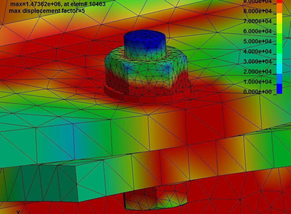
In one of our worked examples, a W8x40 is bolted to a WT4x20 with four 5/8″ bolts in 3/4″ holes, preloaded to 80,000 psi. Members, bolts, nuts and washers are meshed with solid elements, refined at the bolts. Threads are left out: modeling them is computationally exhaustive, and bolt loads can be compared with published nominal capacities.
Bolt-to-nut threads are bonded contacts; every other interface is a separate frictional contact, so the load in each can be recovered. The 300-kip load ramps up in 0.01 seconds, so the run is transient, in LS-DYNA, an explicit solver that handles the stiffness change when the joint separates.
Two Checks Before Any Result
First the contacts: one missing washer-to-nut contact left only three of the four bolts carrying load. Then the preload: the model gave 25 kips per bolt against 24.5 kips by hand (0.307 in² at 80,000 psi).
The full walkthrough is in FEA modeling of bolted connections under external loads, and the hand-calculation side in bolted connections.



HSS Connections
A wide-flange connection usually delivers load into a web or flange that is stiff in that direction. A hollow structural section often takes it on an unstiffened wall that bends out of plane, so the wall, not the bolt or weld group, can govern.
Access is the other problem. A closed section cannot be reached from inside, so the joint needs through-bolts, welded plates or a cap plate, decided before fabrication.
Connections in Delegated Design
Connections are often handled through delegated design: the engineer of record sets member sizes, reactions and design intent, and a specialty engineer develops the joints with the fabricator. Our delegated design services include design validation in SolidWorks and ANSYS and coordination with suppliers and fabricators for manufacturability.

Scoping a Connection
Send the contract drawings with member sizes and reactions, the governing load combinations, the steel grades and bolt specifications, and anything the fabricator has already fixed, such as shop equipment, shipping limits or erection sequence. If a joint is already detailed and something looks wrong, send the detail and say what concerns you.
AISC 360 governs the design of steel members and connections, ASCE 7 sets the loads and AWS D1.1 covers structural welding. Confirm which editions your jurisdiction has adopted before design starts.
Related: structural engineering services, FEA consulting and our structural steel design guide.
Common Questions
What is steel connection design?
The sizing and checking of the bolts, welds, plates and stiffeners that transfer force between steel members, so each joint carries its reactions within code limits and can still be fabricated and erected.
When does a steel connection need finite element analysis?
When the real load path is not the one a standard check assumes: preloaded joints, joints that may separate, prying, HSS joints governed by the section wall, unusual geometry, and impact or cyclic loading. Routine shear tabs and clip angles are covered by published capacities.
Who designs the connections, the engineer of record or a specialty engineer?
Either. On many steel projects a specialty engineer develops the connections under delegated design, working from the design intent, member sizes and reactions set by the engineer of record, in coordination with the fabricator.


