Part 2: The FEA Workflow – From CAD to Simulation
Introduction
In Part 1, we introduced Finite Element Analysis (FEA) as a powerful computational tool used to predict how products behave under real-world forces, heat, vibration, and other physical effects.
Now let’s get practical.
How does a digital 3D model transform into actionable engineering insight? What steps turn a CAD file into a stress map? In this post, we’ll walk through the standard FEA workflow—from preparing geometry to interpreting results—and spotlight the tools and decisions that make or break a successful simulation.
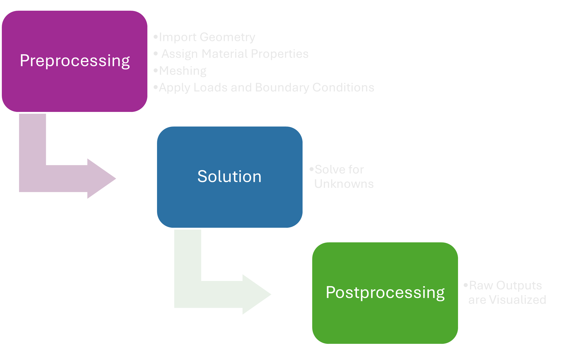
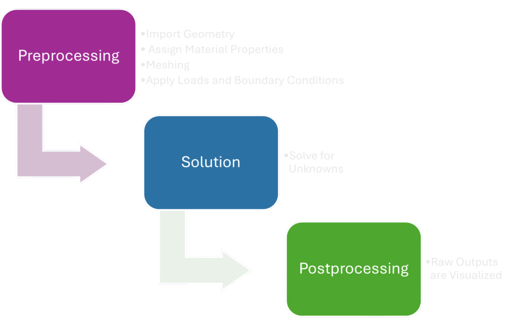
🔧 Step 1: Preprocessing – Building the Simulation Model
Preprocessing sets the foundation. It’s where you define the physics of your problem, simplify the model, and set the stage for accurate results.
✅ 1. Import or Create Geometry
Start with a 3D model. This can be imported from CAD software (like SolidWorks, CATIA, Fusion 360, etc.) or built directly within your FEA platform.
Why it matters: The geometry defines the problem space. Complex details (e.g., threads, chamfers, tiny fillets) might not meaningfully affect structural performance but will increase mesh size and computation time.
🔍 Pro Tip: Use defeaturing techniques to remove unnecessary details. Many FEA platforms offer automatic geometry clean-up tools.
✅ 2. Assign Material Properties
FEA simulations are only as good as the material data behind them. Each component must be assigned material behavior parameters. Common properties include:
- Young’s Modulus (E): Elastic stiffness of the material
- Poisson’s Ratio (ν): Ratio of lateral strain to axial strain
- Density (ρ): Essential for gravity or dynamic simulations
- Yield Strength & Ultimate Strength: For failure analysis
- Thermal Conductivity & Expansion: In thermal or coupled simulations
📚 Tip: Use verified data from material libraries or manufacturers. For advanced simulations (nonlinear, temperature-dependent), consider using temperature-dependent material models or custom stress-strain curves.
✅ 3. Meshing – Dividing the Geometry into Finite Elements
This is where the “finite element” in FEA comes into play. Your geometry is discretized into smaller pieces—elements—connected at nodes.
- Finer Mesh: More elements → More accuracy, longer run time
- Coarser Mesh: Fewer elements → Faster computation, reduced precision
⚠️ Critical Insight: Mesh quality directly impacts result accuracy. Common techniques include:
- Refining mesh in areas of high stress gradient (e.g., near holes, fillets)
- Using tetrahedral elements for complex 3D geometries or hexahedral (brick) elements for higher accuracy in simpler domains
- Checking mesh aspect ratio and skewness to avoid distorted elements
Many solvers offer adaptive mesh refinement during the solution step to balance speed and accuracy.
✅ 4. Apply Loads and Boundary Conditions
This step defines the real-world environment for your part.
- Loads: External forces, pressure, acceleration, torque, temperature, etc.
- Constraints: Fixed supports, pinned joints, rollers, symmetry planes
🧩 Important: Boundary conditions are crucial. A model without sufficient constraints may experience rigid-body motion—leading to solver failure.
🌍 Example: A cantilever beam should be fixed at one end, with a load at the other. Miss this constraint, and the beam will “float” freely in space.
🧮 Step 2: Solution – Solving the Math Behind the Model
Once everything is defined, the solver assembles large systems of equations (based on your mesh and boundary conditions) and solves for unknowns—typically nodal displacements.
FEA types vary by complexity:
- Linear static analysis: Quick and assumes small deformations and linear material behavior
- Nonlinear analysis: Accounts for plasticity, large deformation, contact, or nonlinear materials. Requires iterative solvers and more computational power
- Dynamic or transient simulations: Track changes over time (e.g., vibration, impact, thermal cycling)
🧠 Behind the scenes, the solver is often crunching thousands to millions of simultaneous equations—requiring significant RAM and CPU/GPU resources depending on model size.
📊 Step 3: Postprocessing – Interpreting and Validating the Results
Here’s where numbers become insights. The raw outputs—displacements, stresses, strains, heat fluxes—are visualized to help engineers make decisions.
Common Postprocessing Tools:
- Displacement plots: Visualize how your part deflects under load
- Stress plots (e.g., Von Mises): Identify stress concentrations and potential failure regions
- Strain energy density: Pinpoints where energy is being stored in the material
- Factor of Safety (FoS): Compares stress to allowable limits
- Frequency response & mode shapes: For vibration analysis
📈 Watch out: Don’t take colorful plots at face value. Always cross-reference results with analytical estimates or benchmark cases.
🛠 Choosing the Right FEA Tool
There’s no one-size-fits-all. The best software depends on the type of physics, analysis scale, and your background.
| Tool | Strengths |
| ANSYS | Industry-standard, robust for structural, thermal, fluid, and multiphysics problems |
| Abaqus | Excellent for nonlinear problems, advanced material models, and contact simulation |
| COMSOL Multiphysics | Great for academic research, multi-physics coupling (e.g., electrical + thermal) |
| SolidWorks Simulation | Easy to learn, great for quick structural checks during design |
| OpenFOAM | Powerful open-source tool, widely used in CFD (computational fluid dynamics) |
🧪 For beginners, SolidWorks Simulation or Fusion 360 are great entry points. For advanced users, ANSYS or Abaqus offer broader capabilities but steeper learning curves.
🔜 Coming Up in Part 3…
We’ll explore real-world case studies—like simulating a drone arm under dynamic load or predicting thermal stress in an electronics housing.
We’ll also cover:
- Common FEA mistakes (and how to avoid them)
- How to validate your simulation results
- Tips to balance accuracy and efficiency
🚀 Final Thoughts
FEA can seem intimidating, but understanding the workflow demystifies the process. The key is balancing realism with efficiency—simplifying where possible, refining where necessary, and always questioning results.
Thanks for reading!
Feel free to comment with questions, share your own FEA tips, or suggest topics for future posts.