[LATEXPAGE]
- Basic blast loading design concepts
- Differences between hand calculations and Finite Element Analysis
- Blast analysis using Finite Element Analysis
Blast Loading Design Concepts
Determining Blast Loads
- Charge Size, $W$: The amount of energy released by the explosive blast, typically quantified as an equivalent weight of TNT
- Standoff, $R$: Distance between the blast resistant structure and enter of the blast
Blast loading results in a short, but intense positive phase loading followed by a longer, but much less intense negative phase. The negative phase is often neglected because the loads are much lower. The pressure vs. time relationship is nonlinear (shown in red in the figure below) and varies with charge size and standoff distance. A conservative, linear pressure history, shown in green, is often used for simplicity.
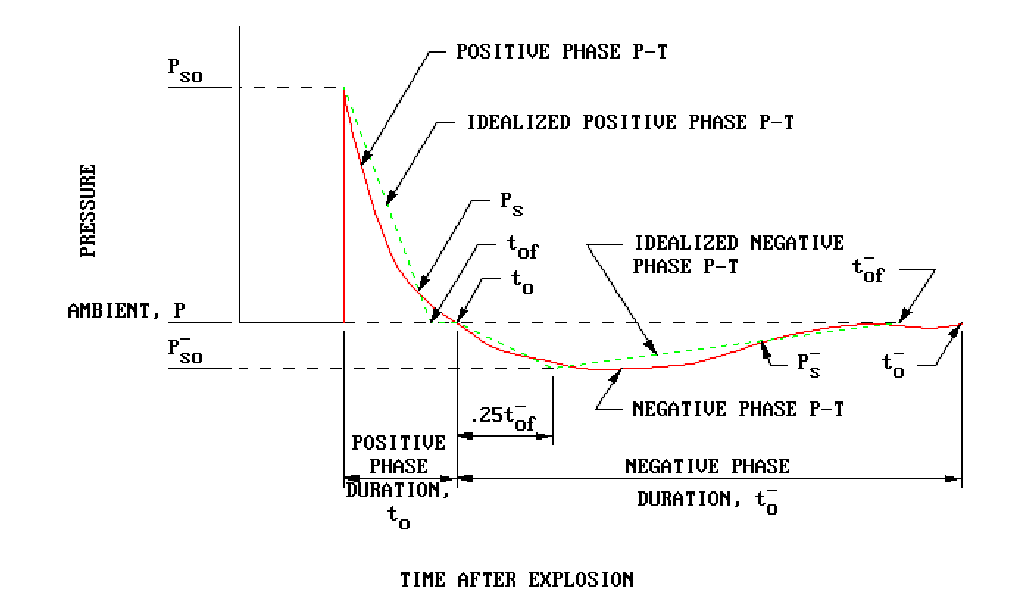
Selected parameters for the curve come from tables such as Figure 2-15 of UFC 3-340-02 (shown below). Parameters in blast engineering are based on the scaled distance, $Z$. Note that parameters and constants are in lbs, psi, m-sec!
\[
Z=\frac{R}{W^{1/3}}
\]

Parameters include:
- Peak Static Overpressure, $P_S_O$ : Peak blast pressure in the free field (neglecting clearing effects).
- Peak Reflected Overpressure, $P_r$ : Peak reflected blast pressure due to structure
- Peak Incident Impulse, $i_s$ : Area under the pressure-time curve, essentially energy carried by the blast wave
- Fictitious Positive Phase Duration, $t_{of}$ : The duration of the positive phase of blast over pressure.
The pressure-time history developed above is for the free field. When the blast wave impacts a structure, the wave is reflected. This reflection amplifies the $P_{SO}$ and is known as Peak Reflected Overpressure, $P_r$.
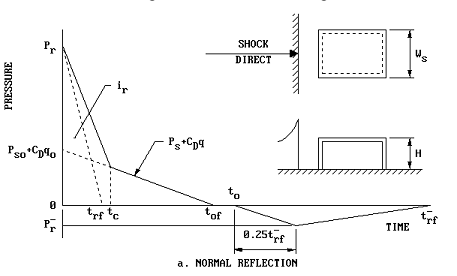
Selected parameters for the curve are calculated based on charge size, standoff and projected frontal area of the structure. Required parameters include:
- Clearing Time, $t_c$ : Time it takes for the reflected blast wave to reach edge of structure from center face
- Positive Reflected Impulse, $i_r$ : Energy carried by the reflected blast wave
- Drag Coefficient, $C_D$ : Drag coefficient, typically $C_D$=1 for front walls of structures
- Peak Dynamic Pressure $q$: Peak dynamic pressure
- Fictitious Reflected Positive Phase Duration, $t_{rf}$ : The duration of the reflected positive phase of blast over pressure.
Two pressure time histories are developed:
- Peak Reflected Pressure History: Developed from the peak reflected overpressure $P_r$ and Fictitious Reflected Positive Phase Duration, $t_{rf}$.
- Peak Dynamic Pressure & Drag Contribution: Developed from the summation of peak static pressure $P_S_O$ and drag contributions $C_D$$q_o$ along with the Fictitious Positive Phase Duration, $t_o_f$
The pressure history with the least impulse (area under the triangular load curve) is used for the analysis of the structure. This is the minimum of $i_r$ and 1/2*($C_D$ $q_o$)*$t_{of}$
Structural Response
The next step is to determine the structural response. Traditional elastic analysis is not suitable as blast loads will cause materials to yield. Blast protection is provided by assuring the structure has the capacity to absorb the blast energy without collapsing. The peak displacement is checked against the maximum permissible ductility.
First we select an idealized structural system, and determine the ultimate resistance (maximum load) for the system.
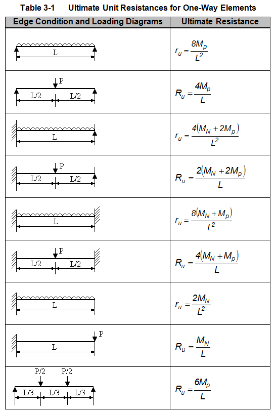
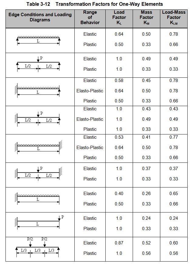
Next we determine the effective natural period of vibration, $T_n$ the system. The natural period is determined as a function of the $K_{LM}$, the Load Mass Factor and $K_E$, the equivalent unit stiffness of the system.
\[
T_n=2\pi\left \{\frac{K_{LM} m}{K_E} \right \}^{1/2}
\]
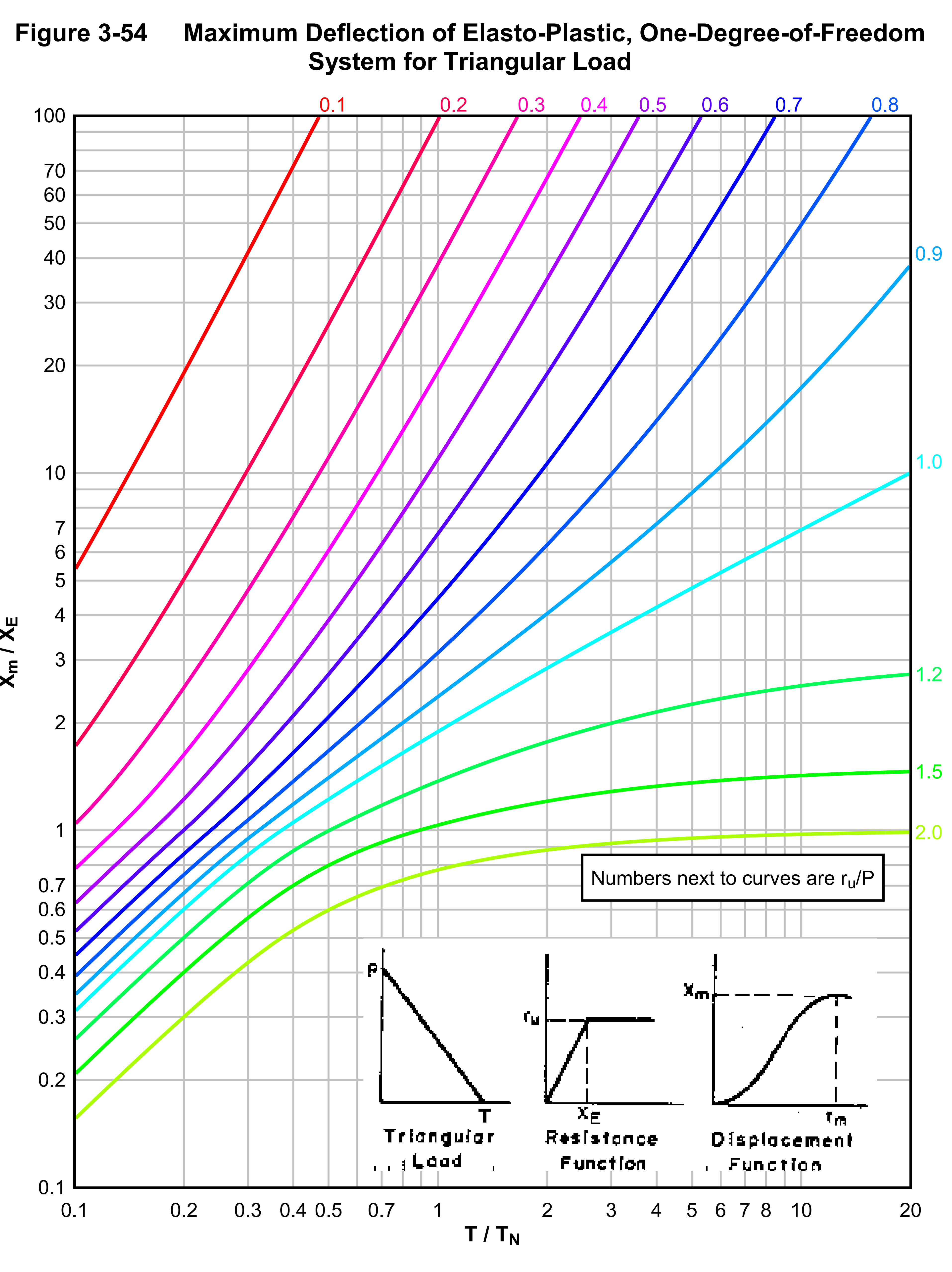
The ductility ratio, $\mu$, in a SDOF system is defined as the ratio of maximum deflection $X_m$, to equivalent elastic deflection, $X_E$. This can be determined from elasto-plastic response graphs. One example is Figure 3-54 of UFC 3-340-02. The maximum displacement is a function of the ratio of applied load to yield load and duration of loading to natural period. Note that we use the chart for a triangular impulse load to mimic the decay of a blast overpressure.
The calculated ductility ratio is then compared to the maximum ductility ratio permitted by the code. These ratios vary by code and material of construction. For purposes of this example, Table 5-8 of UFC 3-340-02 lists the maximum permitted ductility ratio for different structural elements subjected to blast loads. If the calculated ductility ratio is less than maximum permitted the structure provides sufficient protection. If not, the structural response must be re-assessed.

Hand Calculation Drawbacks
- Inability to predict localized stresses
- Failure to predict interaction with adjoining structures
- Inability to evaluateirregular framing systems.
Finite Element Analysis Advantage
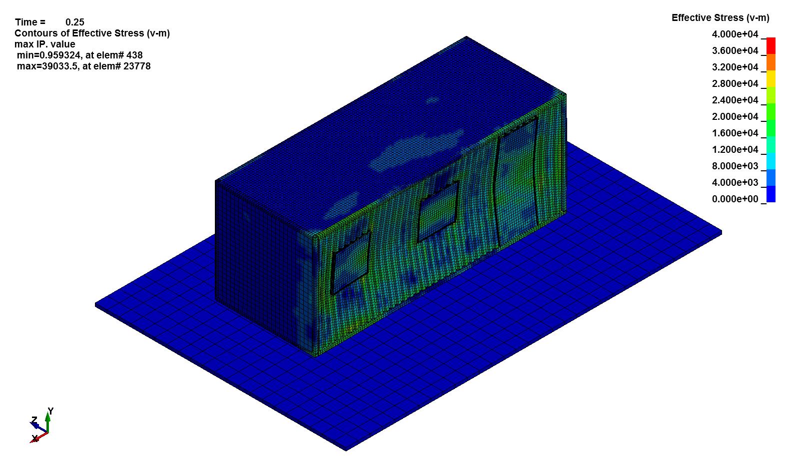
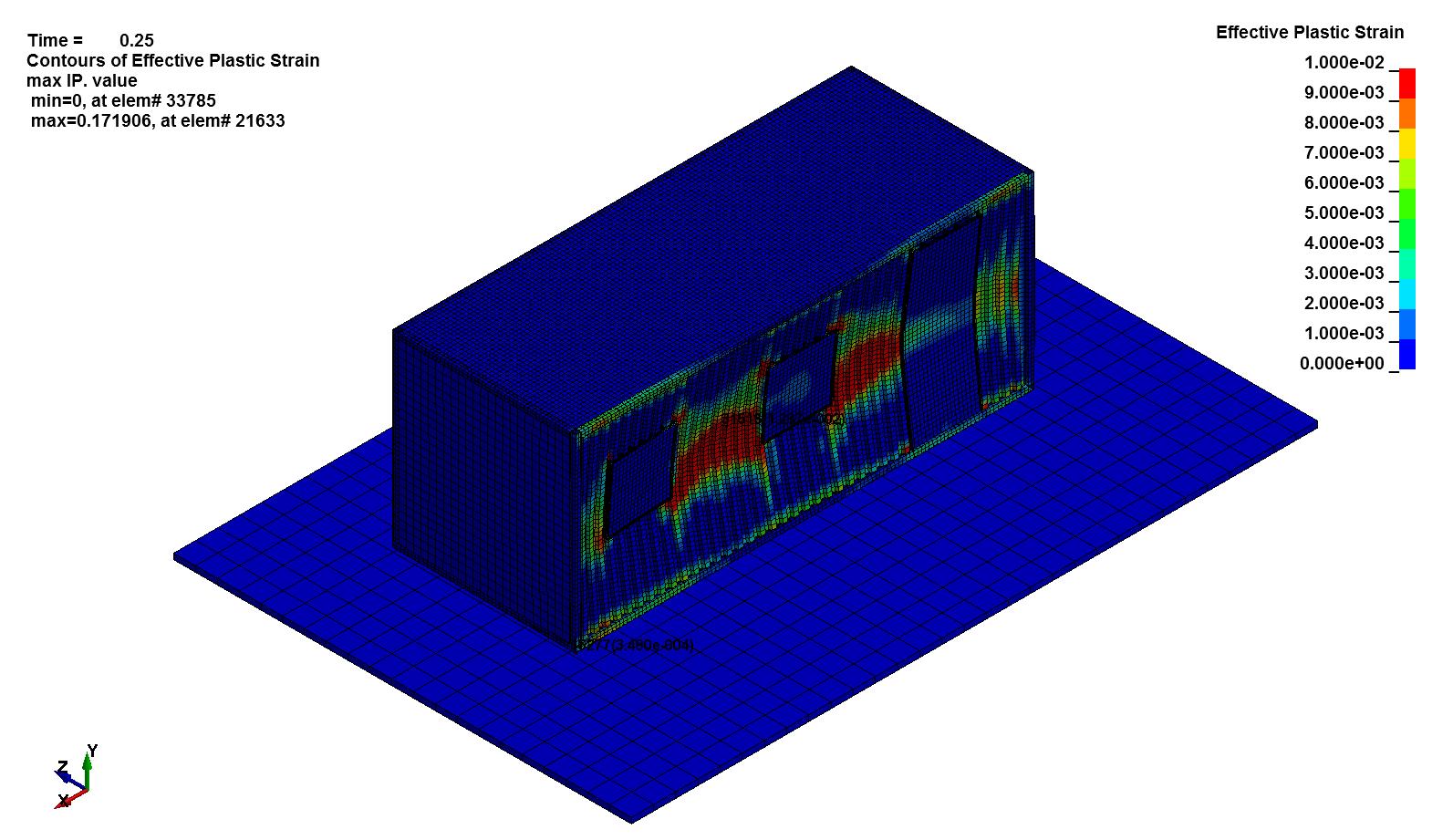
- Irregular Geometry: Framing systems around doors and other openings must carry extra load. FEA predicts the stresses on these critical members.
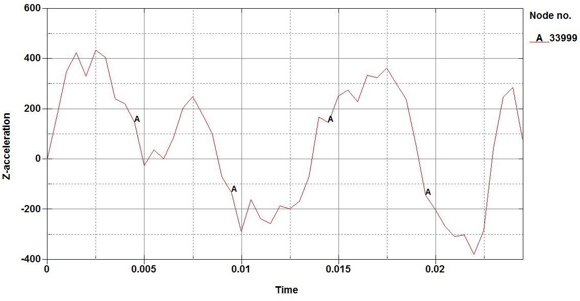
- Secondary Effects: FEA predicts the resulting accelerations and deformation from blasts. This is usedto assess potential internal missile generation following a blast.
Blast Resistant Building Design Example
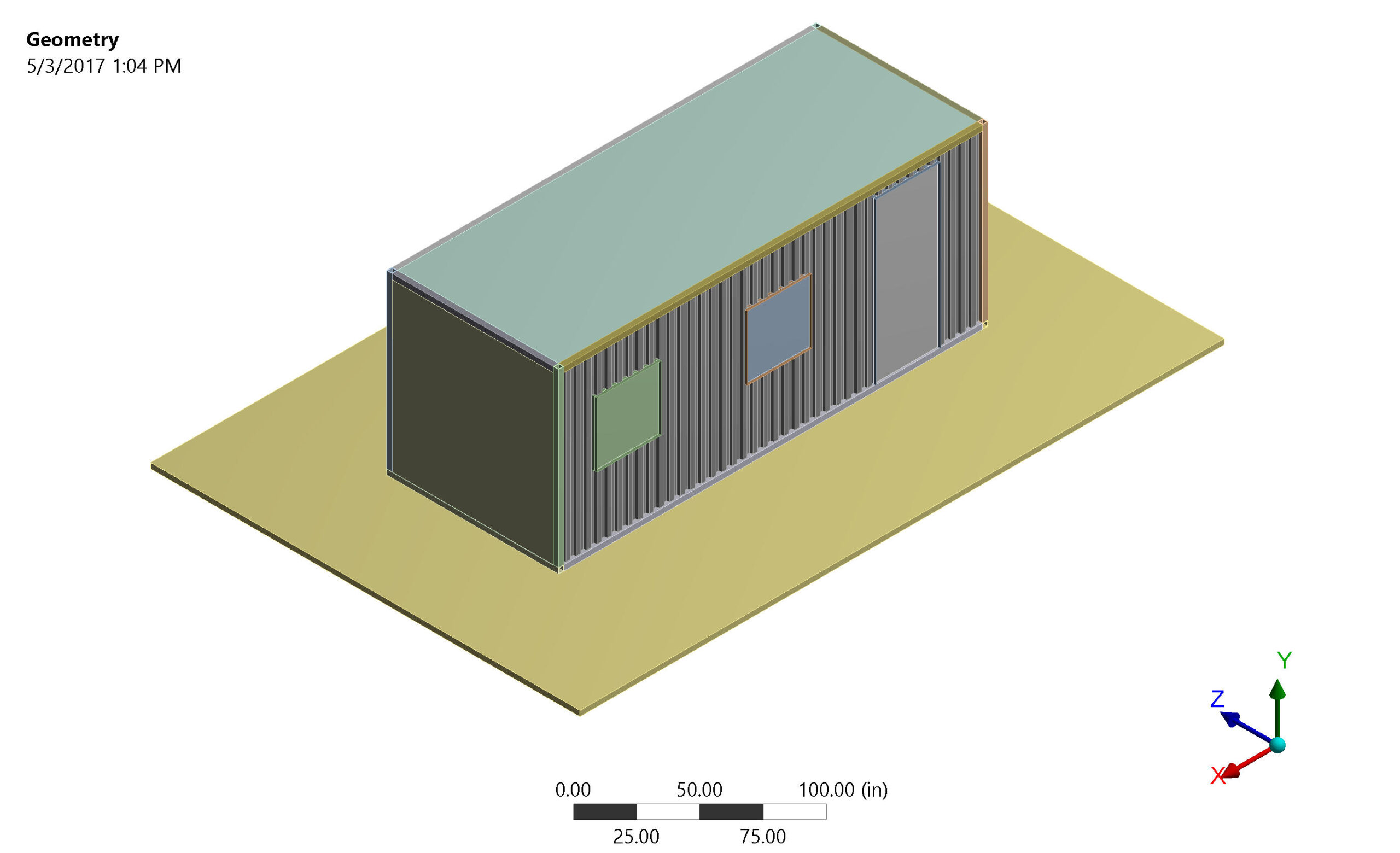
Blast Resistant Building
Blast Loading
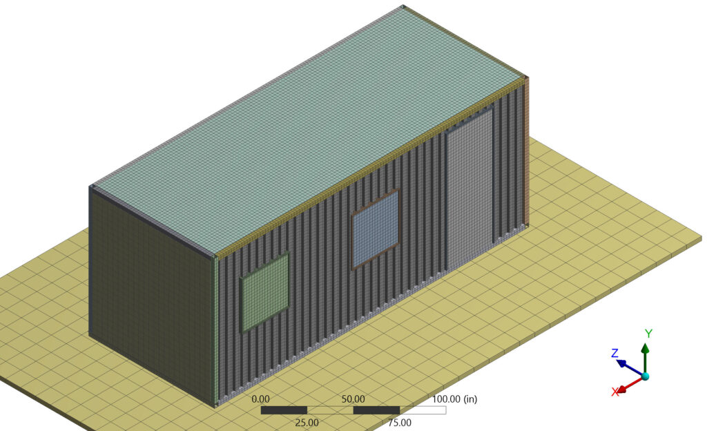
FEA Mesh
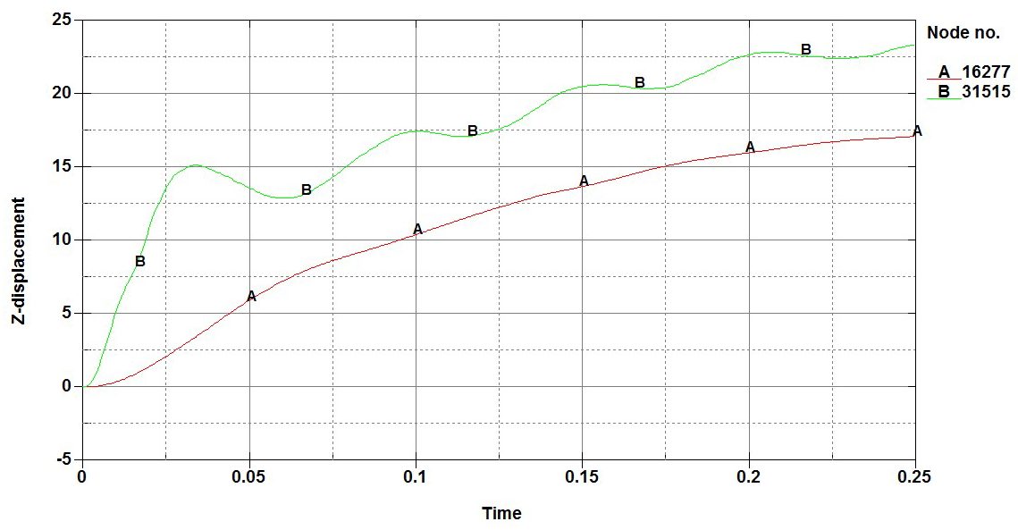
Results

\[
\theta_rotation=\arctan\left \{\frac{7inches}{120inches/2} \right \}=6.7 degrees
\]
Why Finite Element Analysis Leads in Blast-Resistant DesignConclusion
Finite element analysis is the best method for evaluating blast resistant buildings. Only FEA can predict the localized strains, stresses and structural accelerations in complex situations.
Read More!
Blast loading concepts described in this blog were taken from UFC 3-340-02 “STRUCTURES TO RESIST THE EFFECTS OF ACCIDENTAL EXPLOSIONS. This document is used by the U.S. Department of Defense to design their facilities. It is approved for public release with unlimited distribution and can be downloaded here. Recommended reading and worked examples include:
- UFC 3-340-02 Chapter 2: Blast Fragment & Shock Loads
- UFC 3-340-02 Appendix 2: Blast Fragment & Shock Loads: Sample Problem 2A-3 Surface Burst
Let Us Be Your Trusted Partner
- Scoping: Our team of engineers use FEA to develop economicalblast resistant structures. Our scoping process considers cost-saving measures such as offsite fabrication, minimizing welds and protection afforded by existing buildings.
- Fabrication: Our FEA software communicates directlywith CADD geometry and drawings. This communication reduces design and analysis duration.
- Evaluating New Hazards: We use FEA to scope modifications of existing structures for greater hazards. Owners can see substantial savings through small modifications to existing structures.
- Documentation:We understand Quality Assurance. Our team of engineers prepares reports documenting full compliance with code requirements, and our assessments satisfyregulatory and oversight requirements.

