
Home / Services / Steel Connection Design
Steel connection design is the engineering work of sizing and checking the bolts, welds, plates and stiffeners that carry force between steel members, so each joint takes the reactions the frame delivers to it without yielding, slipping, tearing or deflecting past what the structure can tolerate. A member schedule is not a structure until the connections are resolved. The connections are also where most of the fabrication hours sit, which is why a joint that is analytically correct but awkward to weld still costs the project money.
XCEED Engineering works on steel connections from the analysis side: hand calculations and finite element analysis that establish how a joint actually behaves under load, and delegated structural design that turns design intent into a buildable detail.
What XCEED does on steel connections
- Finite element analysis of connections, including preloaded bolted joints modeled with solid elements, with the members, bolts, nuts and washers all present in the model.
- Hand calculations alongside the model, so every analytical result has an independent check behind it.
- Design validation and analysis using SolidWorks and ANSYS.
- Delegated structural and mechanical design, working with owners, engineers of record, contractors and fabricators to turn performance specifications and design intent into fully developed, buildable systems.
- Coordination with suppliers and fabricators for manufacturability, so the detail that leaves the model is one the shop can build.
- Structural steel design from conceptual design through fabrication and installation, by licensed engineers who collaborate with AISC-certified fabricators.
When a connection needs analysis rather than a table check
Most steel joints do not need a model. Shear tabs, clip angles and routine bolted splices are covered by published capacities and standard checks, and running a solid-element model on one is a waste of the project’s money.
The joints worth modeling are the ones where the real load path is not the one the standard check assumes:
- Preloaded joints, where the bolt and the clamped members share the external load and the share depends on their relative stiffness.
- Joints that may separate under load, because separation changes the stiffness of the assembly part-way through the event.
- Prying, where the deformation of a flange or end plate loads the bolt well beyond the applied tension.
- Hollow structural section joints, where the governing limit state is local to an unstiffened chord face rather than to the bolt or weld group.
- Coped, skewed, reinforced or penetrated geometry that no table covers.
- Impact, blast and cyclic loading, where the response is time-dependent.
How a preloaded bolted joint is actually analyzed
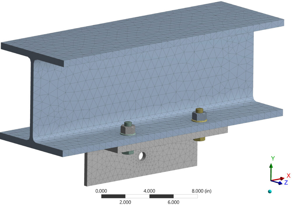
A worked example from XCEED’s own analysis work shows what the method involves. The joint is a W8x40 bolted to a WT4x20 with four 5/8-inch structural bolts in 3/4-inch holes, torqued to an initial preload of 80,000 psi.
The connection is meshed with solid elements and the mesh is refined at the bolt regions to capture the irregular geometry of the bolts and nuts. Threads are deliberately left out. Resolving them would make the model computationally exhaustive, and the structural capacities of bolts and nuts are already well documented, so bolt loads can be compared against published nominal capacities instead.
Contact definition is where these models are won or lost. The threaded bolt-to-nut interfaces are modeled as bonded contact. Every other interface is modeled as an individual frictional contact, which stabilizes the model and lets the load in each interface be recovered separately.
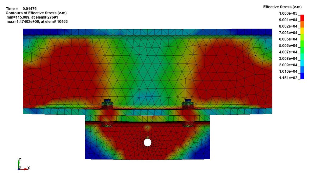
The external load is ramped to 300 kips over 0.01 seconds and held to 0.015 seconds. That makes it a transient problem, and it runs in an explicit solver, LS-DYNA. Explicit solvers are better equipped to accommodate the large change in stiffness that happens when a preloaded joint separates, and joint separation is the event the analysis exists to find.
The two checks that come before any result is reported
First, the contacts. A single missing contact between a washer and a nut left three of the four bolts carrying the external load, visible immediately as uneven stress across the bolt group. Corrected, all four bolts show matching stress. A contact error of that kind does not announce itself in a summary table; it has to be looked for.
Second, the preload. The model returned an initial preload of 25 kips per bolt. The nominal area of a 5/8-inch bolt is 0.307 square inches, and at 80,000 psi of prestress the nominal preload calculates to 24.5 kips. The model reproduces its own input. A model that cannot do that should not be trusted with the external load.
The full walkthrough, with the mesh, the contact surfaces and the stress plots, is in FEA modeling of bolted connections under external loads. The hand-calculation side sits in bolted connections, which works through bolt stiffness, member stiffness and why a joint preloaded to 2.4 kips accepts another 2.66 kips of external tension rather than the 0.45 kips a first guess suggests.
HSS connections and why they behave differently
A wide-flange connection usually delivers its load into a web or a flange that is stiff in the direction of the load. A hollow structural section connection often delivers it into an unstiffened chord face that wants to bend out of plane. That single difference moves the governing limit state away from the bolt or weld group and onto the wall of the section.
It shows up across the whole family: HSS-to-HSS T, Y and K joints, HSS column to wide-flange beam connections, HSS beam to HSS column moment connections, brace connections, column splices and base plates. Chord face plastification, wall slenderness and local deformation decide capacity in cases where a conventional check would report plenty of margin.
Access is the second problem. You cannot reach inside a closed section with a wrench, so the joint has to be resolved with through-bolts, welded plates, a cap plate or a shop-welded detail — a decision made before fabrication, not discovered during it. These are the joints where a refined model earns its cost, because the limit state that governs is a local one.
Where connection design sits in delegated design
On most steel projects, the contract drawings fix the member sizes and the reactions, and the connections are handled through delegated design: a specialty structural engineer works from the design intent set by the engineer of record, alongside the fabricator who has to build the result.
XCEED describes its delegated design services in those terms — transforming performance specifications and design intent into fully developed, buildable systems, in collaboration with owners, engineers of record, contractors and fabricators, with design validation in SolidWorks and ANSYS and coordination with suppliers and fabricators for manufacturability.
Handled well, that arrangement shortens the schedule, because the connection choices are made by the people who know the shop’s equipment and the erector’s sequence. Handled poorly, it leaves a gap where nobody owns a load path. The difference is coordination, and it starts at the first submittal.
Codes and standards
Steel connection design in the United States runs on a coordinated stack rather than one rulebook. AISC 360, the Specification for Structural Steel Buildings, governs the design of steel members and their connections. ASCE 7 defines the loads the structure has to resist. AWS D1.1, the Structural Welding Code for steel, governs how welded connections are qualified, made and inspected. The International Building Code adopts all three by reference, and adoption lags publication, so confirm which editions your jurisdiction has adopted before design starts.
What to send when you scope a connection
The useful starting set is short: the contract drawings with member sizes and reactions, the governing load combinations, the steel grades and bolt specifications, and any constraint the fabricator has already fixed — shop equipment, shipping limits, erection sequence. If the joint has already been detailed and something about it does not look right, send the detail and say what you are worried about. That is usually faster than describing it.
Frequently asked questions
What is steel connection design?
Steel connection design is the sizing and checking of the bolts, welds, plates and stiffeners that transfer force between steel members, so each joint carries the reactions delivered to it within code limits and can still be fabricated and erected. It covers both the strength of the joint and its practicality in the shop.
When does a steel connection need finite element analysis?
When the real load path is not the one a standard check assumes. Preloaded joints, joints that may separate, prying-dominated end plates, hollow structural section joints governed by chord face behavior, unusual geometry, and impact or cyclic loading all fall into that category. Routine shear tabs and clip angles do not; published capacities cover them.
What makes an HSS connection different from a wide-flange connection?
The load usually arrives at an unstiffened closed face that deforms out of plane, so capacity is often governed by the section wall rather than by the bolts or welds. Access is the other difference: a closed section cannot be reached from the inside, which restricts the joint to through-bolts, welded plates or a cap detail decided before fabrication.
Who designs the connections, the engineer of record or a specialty engineer?
Either, and on steel projects it is frequently a specialty structural engineer working under delegated design. The engineer of record sets the design intent, the member sizes and the reactions; the specialty engineer develops the connections from that intent, in coordination with the fabricator.
Which codes govern steel connection design in the United States?
AISC 360 for the design of steel members and connections, ASCE 7 for design loads, and AWS D1.1 for welding. The International Building Code adopts all three by reference, so meeting the IBC means meeting the editions of those standards the code adopts.
Talk to an engineer about a connection
XCEED Engineering and Consulting, P.C. is a structural and mechanical engineering consultancy working on structural steel, connection analysis and delegated design projects across the United States. Related work sits on the structural engineering services and FEA consulting pages, and the wider process is covered in the structural steel design guide.
Send the drawings and the reactions to info@xceed-eng.com, call 585 340 7277, or use the contact page. Questions are answered within 24 hours by email.