
Part 1: The Fundamentals Every Engineer Should Know
🧭 Introduction
In engineering, the bridge between imagination and reality is analysis. It’s what turns a concept on a whiteboard into a functioning aircraft wing, or a suspension bridge. Before we build, we must understand how our designs will behave under real-world conditions—how they’ll stretch, compress, heat up, or crack.
Finite Element Analysis (FEA) is one of the most powerful tools that makes this possible. It transforms the language of physics—governed by complex equations—into actionable insight. With FEA, engineers simulate how a design performs before a single part is manufactured. From drones to offshore wind turbines, if something has to withstand force, heat, vibration, or pressure, FEA can help us understand how it’ll hold up.
In this first part of our FEA series, we’ll dive into the foundational concepts:
- What FEA is (and isn’t)
- Why it’s so widely used
- The key principles that make it work
By the end, you’ll understand not just what FEA does, but why it matters—and how it fits into modern engineering workflows.
📐 What is FEA?
FEA is a numerical simulation technique used to solve complex physical problems. At its core, it’s a way to solve partial differential equations (PDEs)—the equations that describe how things deform, move, or transfer heat—over objects with complex shapes and materials.
These problems arise everywhere in engineering:
- How will a car frame behave in a crash?
- Will a bridge deform too much under heavy traffic?
- Where will a phone case crack if dropped?
Instead of solving these problems with expensive, time-consuming physical experiments, engineers use FEA to run virtual tests—digitally applying forces, heat, or motion to a computer model of the object.
🖥️ Think of FEA as a “digital test lab” that allows engineers to try thousands of scenarios without building a single prototype.
🔍 The Core Idea Behind FEA
So how does it actually work?
Imagine trying to predict how a metal beam bends when loaded. Solving that exactly requires complex equations that are nearly impossible to solve analytically for real-world shapes. This is where FEA comes in.
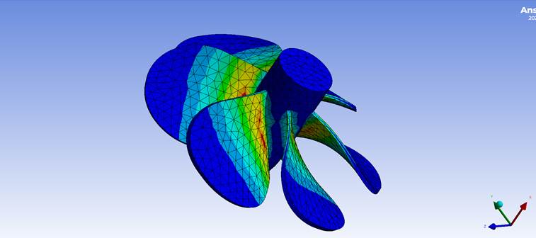
FEA works by breaking down a complex object into smaller, simpler pieces—called finite elements. These are typically tiny triangles in 2D, or tetrahedra and hexahedra in 3D. The idea is that while the whole object might be too complex to analyze, each tiny element is simple enough that we can approximate its behavior with basic equations.
Each element has its own set of equations based on the physics involved (e.g., stress-strain relationships for solid mechanics). FEA assembles these local equations into a global system that models how the entire object behaves when the elements work together.
🔧 Analogy: Think of building a LEGO model. Each block is small and manageable. Put together correctly, they form a complex shape. In FEA, the math for each block is simple—but when combined, they can represent highly realistic behavior.
🧮 The Math Behind the Method (Simplified)
At the heart of FEA is a system of equations that looks like this:
K * u = f
Let’s break that down:
- K: The stiffness matrix. This describes how each part of the object resists deformation. It depends on the material properties and geometry of each element.
- u: The unknown vector. These are the physical quantities we want to solve for—like displacement (how much something bends or stretches), temperature, or velocity.
- f: The load vector. These represent external forces, such as gravity, pressure, or heat.
Solving this system tells us how the object responds:
- Where it deforms the most
- What areas experience the highest stress
- Whether a component is likely to fail
And because it’s all virtual, we can tweak materials, shapes, or loading conditions and instantly re-run the simulation.
🚀 Why Do Engineers Use FEA?
Here’s why FEA has become a cornerstone of modern engineering:
✅ Design Validation Before Manufacturing
Rather than building physical prototypes for every iteration, engineers can simulate how a design will perform and catch flaws early.
✅ Failure Prediction
FEA helps identify where cracks, deformations, or hot spots might occur under extreme conditions—before those failures happen in real life.
✅ Material and Cost Optimization
By simulating stress distribution, engineers can reduce unnecessary material usage, making designs lighter, more efficient, and more sustainable.
✅ Faster Product Development
Simulation lets you iterate rapidly—testing 10 design variations in a day, rather than waiting weeks for prototypes.
🔍 Industries using FEA include:
- Aerospace: Simulating wing loads, turbine blades, thermal stress
- Automotive: Crash testing, engine thermal analysis
- Electronics: Heat flow in circuits, vibration in enclosures
- Civil engineering: Bridges, dams, buildings under seismic loads
🧑🏫 Coming Up in Part 2…
Now that you understand what FEA is and why it matters, the next step is learning how to do it.
In Part 2, we’ll walk through the typical FEA workflow, including:
- Importing a CAD model
- Creating and refining a mesh
- Applying boundary conditions and loads
- Interpreting simulation results
We’ll also discuss how choices like mesh density and boundary conditions can dramatically affect the accuracy of your simulation—and how to avoid the most common mistakes beginners make.
Stay tuned! 🧠⚙️